
CNC Machining for Terminal Components: What the RFQ Must Show
How OEM buyers should prepare a CNC-machined terminal component RFQ covering secondary features, threads, contact zones, burr control, finish, and sample approval.
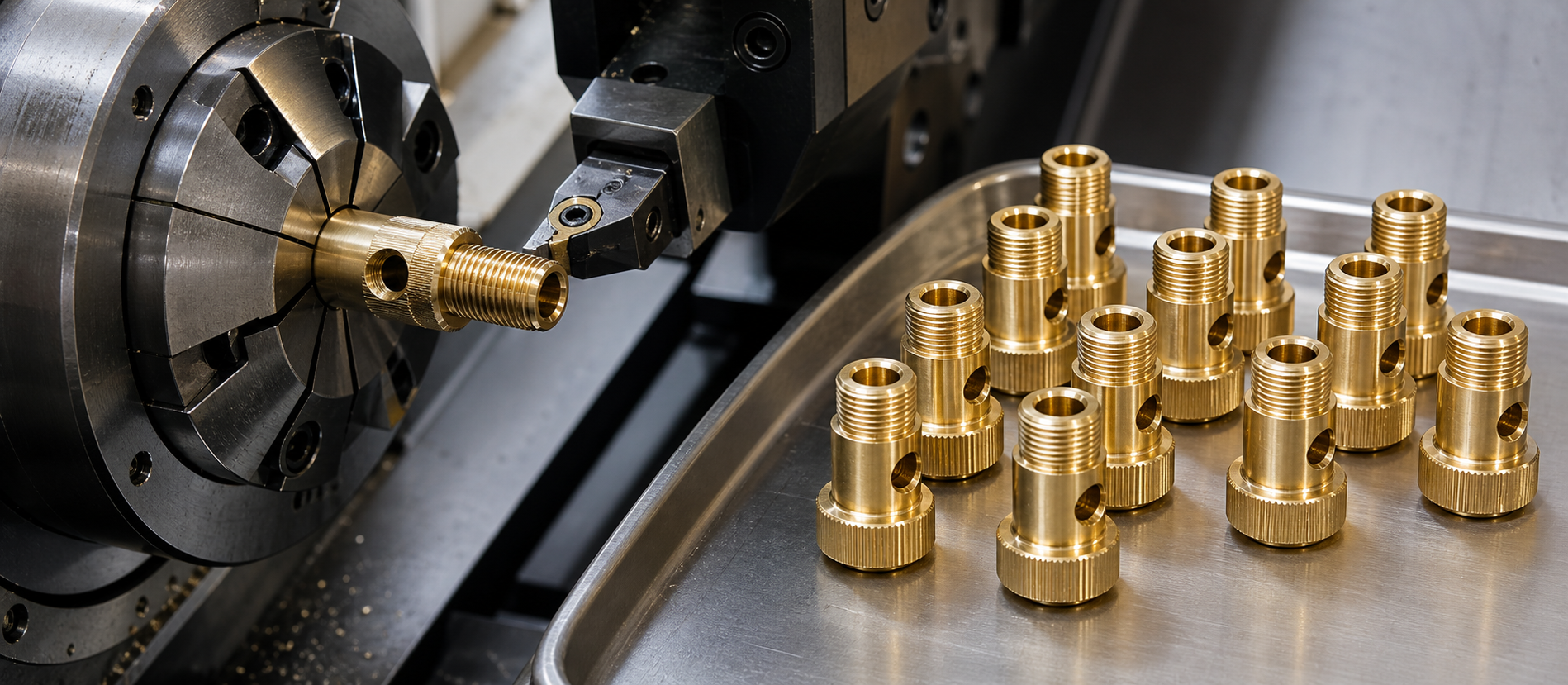
CNC machining for terminal components becomes difficult when the drawing includes more than a round turned body. Cross-holes, milled flats, slots, shoulders, threaded features, insulation seats, and contact surfaces can all change the manufacturing route and the way a sample must be approved.
Our supplier view is direct: do not ask for a “CNC terminal part” from a drawing that does not show which features control the finished interface. A machining process is not the specification. The useful RFQ connects each feature to panel fit, contact, assembly, finish, inspection, and repeat production.
This guide is for OEM buyers sourcing drawing-based brass, copper, and other terminal components. It supports the CNC machining capability page and does not replace product specifications or a project-specific engineering review.
Is the Part Really a Simple Turned Component?
Before choosing a machining route, classify the geometry and the risk. A cylindrical part may still need secondary operations that control the final assembly.
Ask these questions first:
- Does the part have cross-holes, slots, flats, pockets, or non-round faces?
- Which features locate the part in a panel, housing, insulation, nut, washer, plug, lug, or socket?
- Which surfaces carry contact, thread, sealing, appearance, or assembly responsibility?
- Does the drawing require operations after turning, such as drilling, milling, deburring, tapping, or controlled masking?
- What must be checked on the sample before the buyer releases repeat production?
If the answer is “the part is round and only needs turning,” the bar-turned parts guide may be the more precise route. If secondary features change the interface, review the project through CNC machining and the relevant material path.
What CNC Machining Adds to a Terminal RFQ
CNC machining is useful when a terminal component needs controlled features that cannot be described as a simple turned profile. The RFQ should show those features and explain why they matter.
| Feature or decision | What the buyer should show | Why it matters |
|---|---|---|
| Cross-hole or slot | Location, orientation, size, edge condition, and mating part | Can affect cable entry, pin fit, airflow, assembly direction, or burr risk |
| Milled flat | Datum, width, clocking, and contact or wrench function | Can control orientation, tightening, panel clearance, or assembly access |
| Threaded feature | Thread callout, engagement, mating hardware, and functional travel | Finish, burrs, and thread form can affect assembly fit |
| Shoulder or step | Axial location and the part it seats against | Can control panel thickness, washer stack, insulation, or contact position |
| Bore or pocket | Depth, mating component, bottom condition, and inspection basis | Can control socket fit, insert location, or contamination risk |
| Contact face | Exact working surface and finish/handling requirement | Prevents a cosmetic finish note from replacing a functional requirement |
| Appearance zone | Visible surface after assembly and reference sample | Separates visual approval from hidden machining surfaces |
The point is not to force every project into a complicated CNC process. It is to prevent the supplier from quoting the shape while missing the feature that makes the part work.
Mark the Functional Zones on the Drawing
A terminal component drawing should distinguish geometry from function. Not every surface needs the same machining, finish, inspection, or packaging attention.
Mark these zones when they apply:
- Contact zone: the face, bore, edge, pin interface, lug interface, or mating area that participates in the connection.
- Threaded zone: the thread, bore, shoulder, or nut path that controls assembly.
- Panel-fit zone: the shoulder, mounting surface, washer seat, or hole that locates the part in the equipment.
- Insulation zone: the surface that mates with a cap, bushing, sleeve, molded component, or panel insulation.
- Protected zone: an area that must be masked, protected, or reviewed separately during machining or finishing.
- Appearance zone: the surface visible after the equipment is assembled.
- Burr-sensitive zone: a hole, slot, cable entry, contact edge, or mating edge where a burr could affect fit or handling.
For brass hardware, connect the drawing to custom brass components and brass machining. For conductive copper parts, review custom copper components and copper machining.
Threads, Cross-Holes, and Burr Control
Secondary features often create more RFQ risk than the main turned diameter. The buyer should identify which features are functional and which are only visual or noncritical.
Thread and Mating Fit
Include the mating nut, screw, plug, socket, or panel hardware when thread travel or assembly feel matters. State whether the thread is for fastening, adjustment, contact, or a removable service interface.
Do not describe a thread only as “standard” if the drawing, mating component, or project requires a specific callout. If the exact tolerance or inspection method is a buyer requirement, send it for project review; this article does not assign an Axiterm tolerance or inspection result.
Cross-Holes and Slots
Cross-holes and slots can affect cable entry, pin engagement, orientation, insulation clearance, and burr removal. Mark their relationship to the datum, the assembly direction, and any component that passes through them.
If a hole is a contact feature, identify the contact surface. If it is only a clearance or assembly feature, say so. The same hole geometry can have a different production risk depending on its role.
Burrs and Edge Conditions
Do not hide burr control inside a generic “high quality” instruction. Identify the edges that could affect contact, cable entry, insulation fit, operator handling, or mating hardware. Include the sample approval method for those edges when the buyer has a visual or functional acceptance rule.
Material and Finish Must Follow the Machining Route
Material and finish decisions should be reviewed with the geometry, not added after the machining route is chosen.
For the material section, state:
- the required material or alternatives still under review;
- whether the material affects contact, machining, weight, appearance, or assembly;
- whether the material is fixed by an existing drawing, sample, or equipment requirement.
For the finish section, state:
- the requested finish or reference sample;
- contact, appearance, threaded, protected, and masked zones;
- whether finish approval is visual, dimensional, functional, or combined;
- whether the finished part must be checked again with mating hardware.
Use the plating and finish review path when coating coverage, masking, contact surfaces, or appearance approval is central. Do not infer plating thickness, corrosion result, certification, electrical rating, or test performance from a finish name or a photograph.
What Should the CNC RFQ Package Include?
Send a compact package through the RFQ page:
- Drawing or marked sample with revision and critical feature callouts.
- Material requirement or clearly labeled material decision still open.
- Mating parts: nut, screw, plug, lug, socket, panel, enclosure, insulation, or cable when relevant.
- Contact, thread, panel-fit, insulation, appearance, protected, and burr-sensitive zones.
- Machining features requiring secondary operations, such as holes, slots, flats, pockets, tapping, or deburring.
- Finish requirement and reference sample, with zones separated by function.
- Prototype, sample, pilot, repeat-order, or forecast quantity stage.
- Inspection points and sample approval method.
- Packaging requirement for visible, plated, threaded, or contact-sensitive surfaces.
- Any buyer-specified tolerance, test, certification, MOQ, or lead-time requirement for separate confirmation.
If the design is still changing, route it through OEM terminal development so machining, material, finish, insulation, assembly, and release decisions remain connected.
CNC RFQ Gaps That Cause Rework
| RFQ gap | What can go wrong | Better input |
|---|---|---|
| Drawing shows shape but not function | Supplier cannot tell which surface controls the interface | Mark contact, panel-fit, thread, insulation, and appearance zones |
| Cross-hole has no datum or orientation | Cable, pin, or assembly direction is misunderstood | Add datum, clocking, mating part, and edge requirement |
| Thread has no mating hardware | Finished part looks correct but does not assemble as expected | Send nut, screw, plug, socket, or panel reference |
| Burr requirement says only “deburr” | Critical edge condition is interpreted differently | Identify burr-sensitive edges and sample acceptance basis |
| Finish is specified by color only | Contact and masked surfaces are not controlled | Separate finish zones and provide reference sample |
| Quantity has no project stage | Prototype and repeat-production assumptions are mixed | State prototype, sample, pilot, repeat, or forecast stage |
| Packaging is defined late | Threads, finish, or visible surfaces are damaged in transit | Include packaging protection in sample release |
These are not abstract process concerns. They are the questions that decide whether a CNC quote can move cleanly into sample approval and repeat production.
Sample Approval for CNC Terminal Components
The sample should prove the interface, not only the outline. Before release, review:
- Geometry basis: critical dimensions, holes, slots, flats, shoulders, bores, and threads match the approved drawing revision.
- Interface basis: the part works with the intended panel, plug, lug, nut, screw, socket, cable, or insulation component.
- Zone basis: contact, protected, threaded, panel-fit, insulation, appearance, and burr-sensitive zones are understood.
- Finish basis: visible and functional surfaces match the approved requirement or are clearly marked for further review.
- Assembly basis: the part can be handled, tightened, inserted, or assembled in the intended sequence.
- Packaging basis: sensitive surfaces and variants remain protected and identifiable.
- Revision basis: drawing, sample photos, inspection notes, and packaging reference remain tied to one release record.
If the project needs a complete hardware set or pre-assembly, connect the machining review to terminal component assembly. A machined component can be correct by itself and still fail the equipment review when the larger set is not controlled.
When CNC Machining Is the Right Review Path
Use the CNC machining path when secondary features, multi-axis relationships, holes, slots, flats, pockets, threads, or interface surfaces require coordinated review.
Use the bar-turned support path when the main question is a simple turned profile and its mating fit. Use brass or copper capability pages when material route is the main decision. Use OEM terminal development when the part is still being defined as part of a new interface. Use the RFQ page when the buyer has a drawing, sample, application, quantity stage, or finish requirement ready for review.
The correct route is decided by the part’s role and evidence, not by the keyword used in the first email.
Frequently Asked Questions
Is CNC machining the same as bar turning?
They can overlap, but they are not the same RFQ emphasis. Bar turning highlights a round part made from bar stock. CNC machining may include turning plus drilling, milling, slots, flats, pockets, tapping, or other secondary features. The drawing and interface decide the review path.
What should I mark on a CNC terminal drawing?
Mark contact zones, threaded zones, panel-fit surfaces, insulation interfaces, protected areas, appearance zones, burr-sensitive edges, datums, and features that need a mating-part check.
Do I need to send the mating hardware?
Send it when thread travel, contact, panel fit, washer stack, insulation, cable entry, or assembly acceptance depends on it. A loose-part check cannot establish every assembled relationship.
Can Axiterm confirm CNC tolerances from this guide?
No. Exact tolerances, inspection methods, and acceptance values depend on the buyer’s drawing, sample, mating interface, and project evidence. They require separate engineering review.
When should CNC machining be reviewed with plating or assembly?
Review them together when finish zones, masking, protected threads, visible surfaces, molded insulation, washers, nuts, labels, or packaging can affect the released terminal assembly.
Source and Review Boundary
This article uses Axiterm’s CNC Machining, Brass Machining, Copper Machining, Custom Brass Components, Custom Copper Components, Plating, Assembly, OEM Terminal Development, and RFQ pages as the source for the review path. It supports /capabilities/cnc-machining/ and does not replace product specifications.
Method and limitation note: final machining route, material, dimensions, tolerances, inspection method, finish, certification, MOQ, lead time, packaging, and release approval depend on the buyer’s drawings, samples, mating interfaces, equipment context, and project evidence. No Axiterm tolerance, rating, certification, test result, inspection-equipment claim, MOQ, lead time, or customer case is claimed here. Reviewed by Gben, Marketing Manager.