
OEM Terminal Component Quality Inspection Plan
How OEM buyers can define a practical inspection and approval plan for terminal components using drawings, samples, critical features, finish zones, packaging, and revision control.
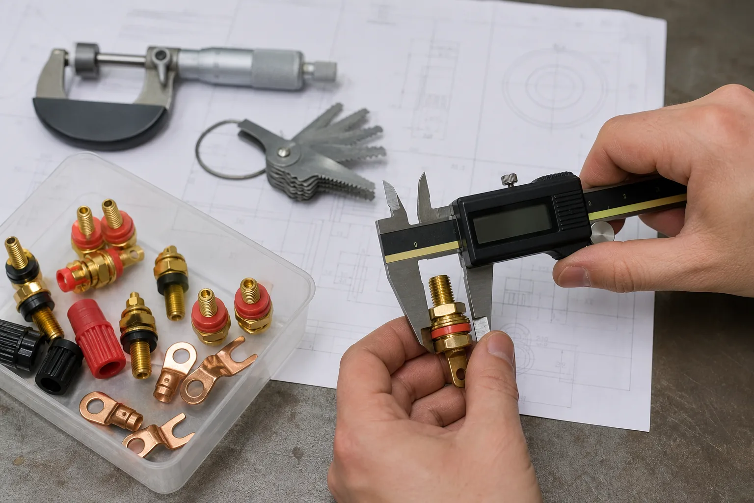
An OEM terminal component quality plan should connect the drawing, sample, critical features, inspection method, finish zones, packaging, and approval owner. The goal is not to create a generic inspection checklist; it is to make the acceptance basis clear enough that the approved sample and repeat-production parts can be compared against the same revision.
The OEM terminal development page is the primary owner for supplier qualification and quality-development context. This article supports that page and routes project-specific requirements to the RFQ page. It does not claim a universal Axiterm inspection standard, certification, tolerance, test result, or inspection-equipment capability.
What Should an OEM Quality Plan Define?
Start with the part’s role and release basis:
- Part identity: part number, drawing revision, material route, finish route, and variant.
- Functional interface: panel, wire, cable, lug, plug, probe, PCB, enclosure, or mating hardware.
- Critical features: dimensions, threads, contact zones, mounting features, insulation interfaces, and marking.
- Inspection basis: drawing characteristic, approved sample, visual reference, fixture, or buyer-supplied method.
- Release owner: buyer, engineering reviewer, supplier quality contact, or change-control owner.
- Packaging and traceability: labels, lot separation, protective packaging, and revision identification.
If a value or test method is not approved, mark it TBD or “buyer to define.” A quality plan should expose missing decisions rather than silently inventing acceptance limits.
Build the Inspection Plan Around the Drawing
The drawing should be the starting point for inspection planning, not a document attached after production. Mark the features that can affect fit, connection, assembly, or release:
| Feature group | Inspection question |
|---|---|
| Mounting geometry | Does the part fit the panel, bracket, enclosure, or fixture shown in the drawing? |
| Threads and hardware | Are thread form, engagement, nut, washer, spacer, and tool-access requirements defined? |
| Contact interface | Which face, bore, post, lug, or mating surface must be compared or checked? |
| Insulation | Are shoulders, bushings, caps, spacers, barriers, and clearances identified? |
| Finish zones | Which surfaces are contact, threaded, masked, protected, or appearance-only? |
| Identification | Are polarity, channel, color, label, part number, and revision requirements visible? |
| Assembly | Does the part arrive loose, as a kit, or as a pre-assembled unit? |
This map tells the buyer what needs evidence. It does not establish a tolerance or pass/fail limit unless the approved drawing or inspection method provides one.
Separate Critical, Major, and Visual Checks
Not every feature needs the same review treatment. A practical plan separates checks by decision impact:
- Critical interface checks: features that determine mounting, mating, insulation fit, or assembly completion.
- Major dimensional checks: features that affect repeatability, hardware engagement, routing, or enclosure clearance.
- Finish and appearance checks: visible surfaces, contact zones, protected areas, masking, color, and sample comparison.
- Identification and packaging checks: labels, variants, revision, lot separation, protective packaging, and completeness.
The buyer should define the inspection method and acceptance basis for each group. Do not label a feature “critical” without explaining the interface or release risk it controls.
Use the Approved Sample as a Reference, Not a Substitute for the Drawing
Samples are useful for checking the complete relationship between a terminal component and its mating parts. They should be linked to the drawing revision and approval record.
Review the sample in the representative assembly where possible:
- panel or enclosure opening;
- mating plug, lug, wire, cable, probe, or PCB;
- insulation, shoulder, bushing, cap, and hardware stack;
- front access, rear clearance, tool access, and cable routing;
- finish zones, labels, polarity, and appearance reference;
- packaging, part separation, and revision marking.
The sample demonstrates the approved reference at a stated revision. It does not automatically prove a new performance claim, certification, environmental qualification, or production capability.
Define Material and Finish Evidence Separately
Material and surface finish should not be reduced to a single line such as “brass with plating.” Record what is fixed and what still needs review:
- material family or buyer-approved grade;
- contact, threaded, masked, protected, and appearance zones;
- finish name and visual or physical reference;
- machining, forming, molding, or assembly route;
- packaging and handling requirements for finished surfaces;
- inspection or test evidence required for release;
- responsible reviewer for open material or finish decisions.
Use the brass versus copper terminal guide for material decisions and terminal component plating finish zones for contact, appearance, protected, and masked surfaces. A material or finish name alone does not prove conductivity, corrosion performance, adhesion, thickness, or certification.
Create a Supplier-Ready Quality Record
| Record | Minimum information |
|---|---|
| Drawing register | Part number, revision, date, marked characteristics, and change owner |
| Sample record | Sample identifier, photos, mating context, open issues, and approval status |
| Inspection plan | Feature, method, reference, responsibility, and required evidence |
| Material/finish record | Requirement, zone, source, reference sample, and unresolved items |
| Assembly review | Hardware set, sequence, fit, access, insulation, and completeness |
| Packaging record | Part separation, label, protection, lot, and revision information |
| Change record | Requested change, affected feature, new sample need, and approval owner |
| RFQ package | Drawing, sample, quantity range, application, project stage, and schedule assumptions |
Keep TBD, DATA NEEDED, and “buyer approval required” visible in the record. This is more useful than filling the field with an unsupported default.
Control Revision and Change Approval
Quality problems often begin when the drawing, sample, packaging, and supplier instruction no longer describe the same part. Before repeat production or a supplier change, confirm:
- the active drawing revision;
- the sample or visual reference linked to that revision;
- the material and finish route;
- the inspection points affected by the change;
- the packaging and label version;
- whether a new sample or buyer approval is required;
- who can release the change.
Do not treat an informal email, photo, or verbal instruction as a permanent revision unless the project owner adopts it into the controlled record.
Common Quality-Planning Mistakes
| Mistake | Risk created | Better action |
|---|---|---|
| Using a generic inspection checklist | Important interface features remain undefined | Start from the drawing and installed assembly |
| Treating the sample as the whole specification | The sample revision and acceptance basis can be unclear | Link sample, drawing, photos, and approval record |
| Mixing contact and appearance requirements | A visible finish statement may be applied to the wrong zone | Mark contact, thread, masked, protected, and appearance zones |
| Hiding open decisions | Unsupported limits or assumptions enter production | Record TBD or DATA NEEDED with an owner |
| Ignoring packaging and labels | Variants, revisions, or finished surfaces can be mixed or damaged | Review packaging as part of quality release |
| Changing a feature without a new review | Approved sample no longer represents repeat production | Trigger change review and sample approval where needed |
Route Quality Review to the Right Owner
- Use OEM terminal development for supplier qualification, drawing review, quality planning, and revision control.
- Use custom terminal components for drawing-based parts outside a standard family.
- Use terminal component sample approval for sample fit, finish, packaging, and release checks.
- Use terminal component assembly when kits, pre-assembly, packaging, or completeness are part of the requirement.
- Use plating capability when finish zones and process boundaries need separate review.
- Use the RFQ page to send the drawing, sample, application context, quality requirements, quantity range, and project stage.
Frequently Asked Questions
What is the first input for a terminal component quality plan?
Start with the current drawing revision and the installed interface. Add the sample, mating hardware, material and finish requirements, critical features, inspection basis, packaging, and approval owner.
Is an approved sample enough to release repeat production?
Not by itself. The sample should be linked to the drawing revision, inspection basis, packaging, open issues, and change-control owner before repeat production is released.
Who defines tolerances and pass/fail limits?
The project drawing, buyer-approved inspection method, or engineering reviewer must define them. This article does not invent tolerances or assign a universal Axiterm limit.
Can quality requirements be reviewed before an RFQ?
Yes. Send the drawing, sample or photos, mating hardware, application context, expected quantity range, finish requirements, and open quality questions for engineering review.
Source and Review Boundary
This article uses Axiterm’s OEM Terminal Development, RFQ, Sample Approval, Materials, Plating, Assembly, and Custom Terminal Components routes as the source path. It is a supplier-qualification and quality-planning support article, not a public inspection specification.
Method and limitation note: the inspection plan depends on the buyer’s drawing, sample, interface, material and finish requirements, validation method, and change-control process. This article does not claim Axiterm certifications, exact tolerances, inspection equipment, test results, MOQ, lead time, production capacity, or customer outcomes. Reviewed by Gben, Marketing Manager; engineering review remains required for performance-sensitive requirements.